CMPUT 503 Exercise 1
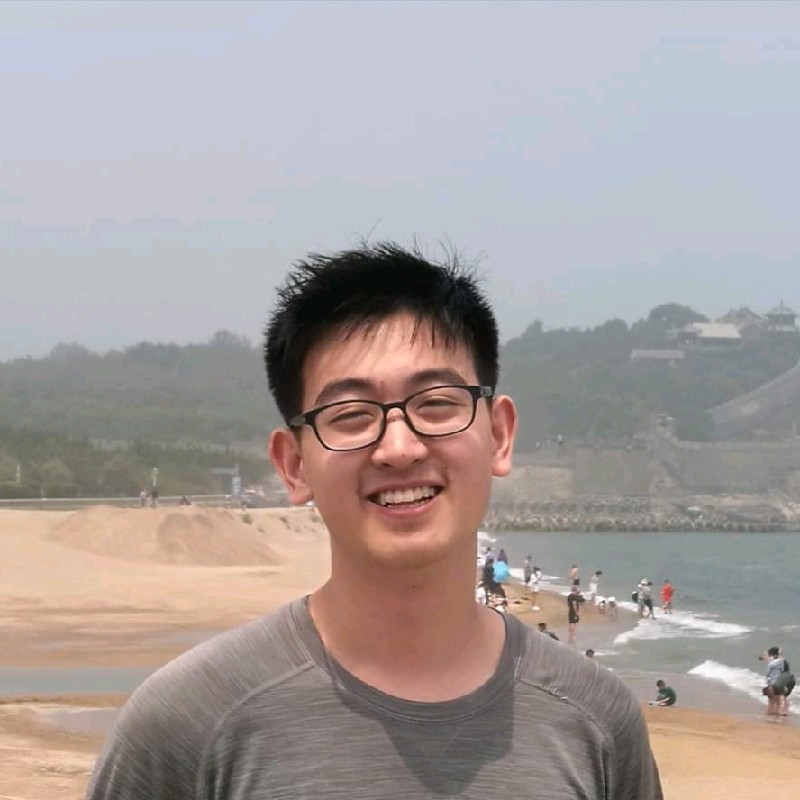
Dashboard
The image shows the DuckieTown dashboard of our duckiebot (csc22936). On the top are the motor signals, which are linear speed (how many meters the duckiebot is moving per second), motor speed (how fast each motor is moving), and angular speed (how many radians the duckiebot if turning per second). The bottom section shows the camera signal coming from the front camera of the duckiebot at 8 frames per second.
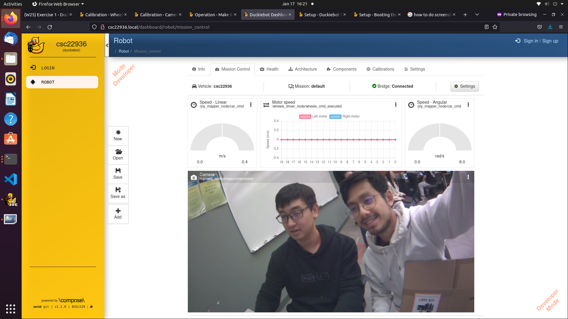
Running the Duckiebot Program
The image shows the output of the program running on the the Docker image built on the duckiebot. The program message = "Hello from %s!" % os.environ['VEHICLE_NAME'] retrieves the environment variable VEHICLE_NAME (in our case csc22936) and prints it onto the terminal.
Calibration

The screenshot shows the instrinsic .yaml file for camera calibration. The intrinsic calibration is done by displaying a predetermined grid pattern to the duckiebot’s camera and allowing the duckiebot to solve for its camera parameters. The values of the matrices shown are used to project 3D points in the world to 2D points in images while considering the influence of the distortion.
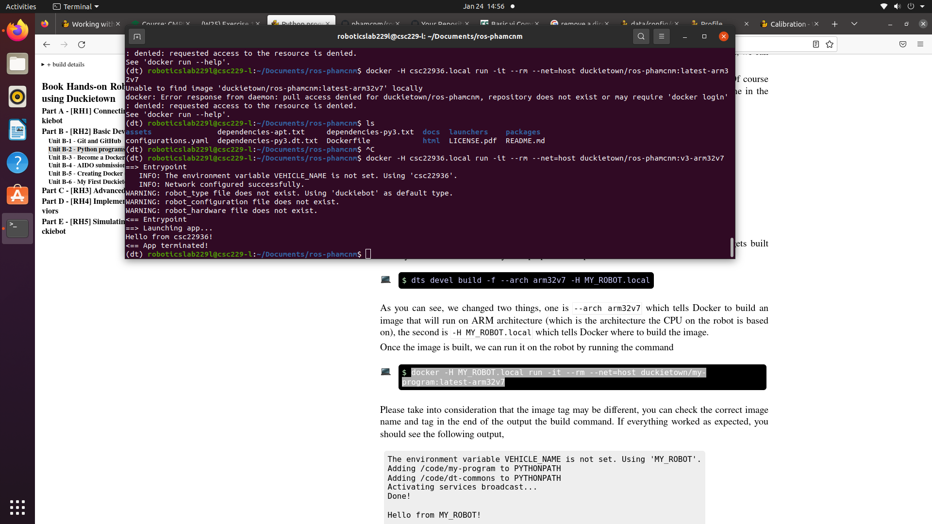
The screenshot shows the extrinsic .yaml file for camera calibration. During the extrinsic calibration, the same grid is displayed facing up from the ground, and the robot is expected to find the homography between the image from the camera and the actual image. The resulting homography parameters are shown in the extrinsic .yaml file.
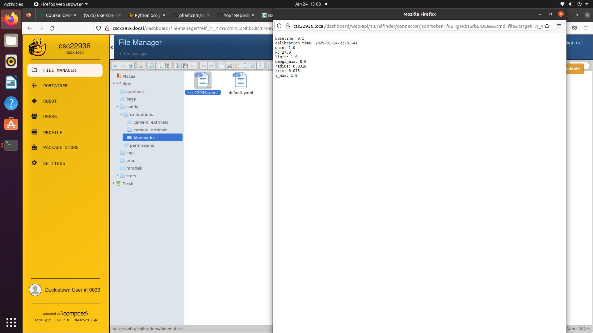
The screenshot shows the kinematics .yaml file for wheel calibration. During the calibration, the duckiebot is expected to complete a 2m long drive while staying in a straight lane. The trim parameter of the duckiebot is changed as the duckiebot has unequal motor or wheels on the two sides. Our final trim value is 0.075 and gain value is left unchanged.
Straight Driving
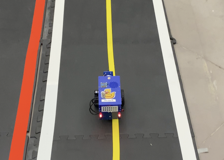
The video shows the duckiebot driving in straight lane for 2 meters. The video is taken after wheel calibration is completed, and the driving force of the two wheels are balanced to a good extent.
Lane Following
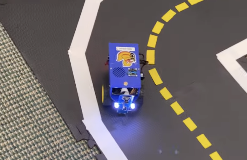
The video shows the duckiebot running the lane following demo. The video is taken after both wheel calibration and camera calibration is completed. The lane following demo is done autonomously by the duckiebot, through line segment detection from cameras and motor control of both wheels. The duckiebot was able to continue to perform the lane following after the video is taken.
Write Up
In this first exercise, we completed the calibration of wheels and camera of the duckiebot, which allowed the duckiebot to perform the 2m straight lane drive and the lane following demo. I believe that the wheels started with unequal power in our case, causing the duckiebot unable to complete a 2m straight drive. After calibration by tuning the trim parameter, the two wheels had a more balanced drive and the duckiebot could drive straight with much less deviation from the centre of the lane. The camera was calibrated in a way that the robot can accurately project points in the 3D world to the 2D image points, accounting for distortion and homography. This enabled the duckiebot to detect line segments on the ground and perform lane following.
Subsequently, I collaborated with my lab mate on creating a Duckietown-compliant Docker image. The docker image provides a more isolated environment for easier program deployment and containerization. We were able to run a python program on duckiebot and receive its output from the local machine.
In the lane following demo, the duckiebot was performing line segment detection on the ground so it could perceive the track that it should be staying in. Ideally, I believe that the duckiebot was trying to find a balanced position between the two boundary lines it detects, and being close to any boundary line would cause it to self-adjust its speed of the wheels so that it returns to a balanced position. In our recorded video, the duckiebot sometimes deviates from the track, typically after a corner, causing it to touch the lines. I think that this is likely due to the fact that the two wheels are not perfectly calibrated and the error causes the duckiebot to turn at an inaccurate angle for its projected movement.
In this lab, we worked on calibration of the wheels and the camera, so that the robot can perform basic tasks (2m straight drive, lane following) with limited error. This sets us up for the future development work for the duckiebot to perform more challenging tasks in a more complex environment. Moreover, being able to deploy docker images and run programs on the duckiebot allows us to directly monitor and control the duckiebot with scripts.
References
Collboration
- I collaborated with Minh Pham on completing all deliverables of the lab, including the aformentioned screenshots and video, as well as github repository
- My questions regarding the lab were answered by TAs of the course
AI Usages
- ChatGPT was used to reword some sentences in this report