CMPUT 503 Exercise 2
Code
Code for excersie 2
Code to customize and annotate camera image is here
Code for the Duckiebot to drive forwards and backwards 1.25 meters is here
Code for Duckiebot to rotate is here
Code to make the Duckiebot travel in a D shape using LEDs to signal state is here
Code to plot your tracked trajectory from rosbag is here
All nodes are shutdown properly in all scripts through the service call: rospy.signal_shutdown("Finished")
Readme updated
ROS Basics
Difference between ROS topics, nodes, services, messages, and bags
Nodes in ROS are running processes that perform certain designated tasks. The idea of using nodes in ROS is to reduce coupling between programs and to provide additional fault tolerance in case any nodes fail. Nodes can be combined into a graph and can communicate with each other using topics, which are channels where messages are sent and received by publishers and subscribers. The messages are data structures with pre-specified typed fields. Nodes can publish messages to the ROS topics, and subscribe to topics to continuously receive and process messages in a decoupled manner. Alternatively, nodes can communicate with each other using services, which provide a synchronous request-response mechanism. A ROS node can provide a service for client nodes to send a request and wait to receive information carried by a single reply. The one-to-one relationship between the request message and the reply message defines the service. The messages used in communication between nodes can be recorded into a bag file in both online and offline settings. In ROS, the data carried by bags can be further processed, analyzed and visualized for better understanding of the robot behaviours.
Screenshot of subscriber info from “Hello from…”
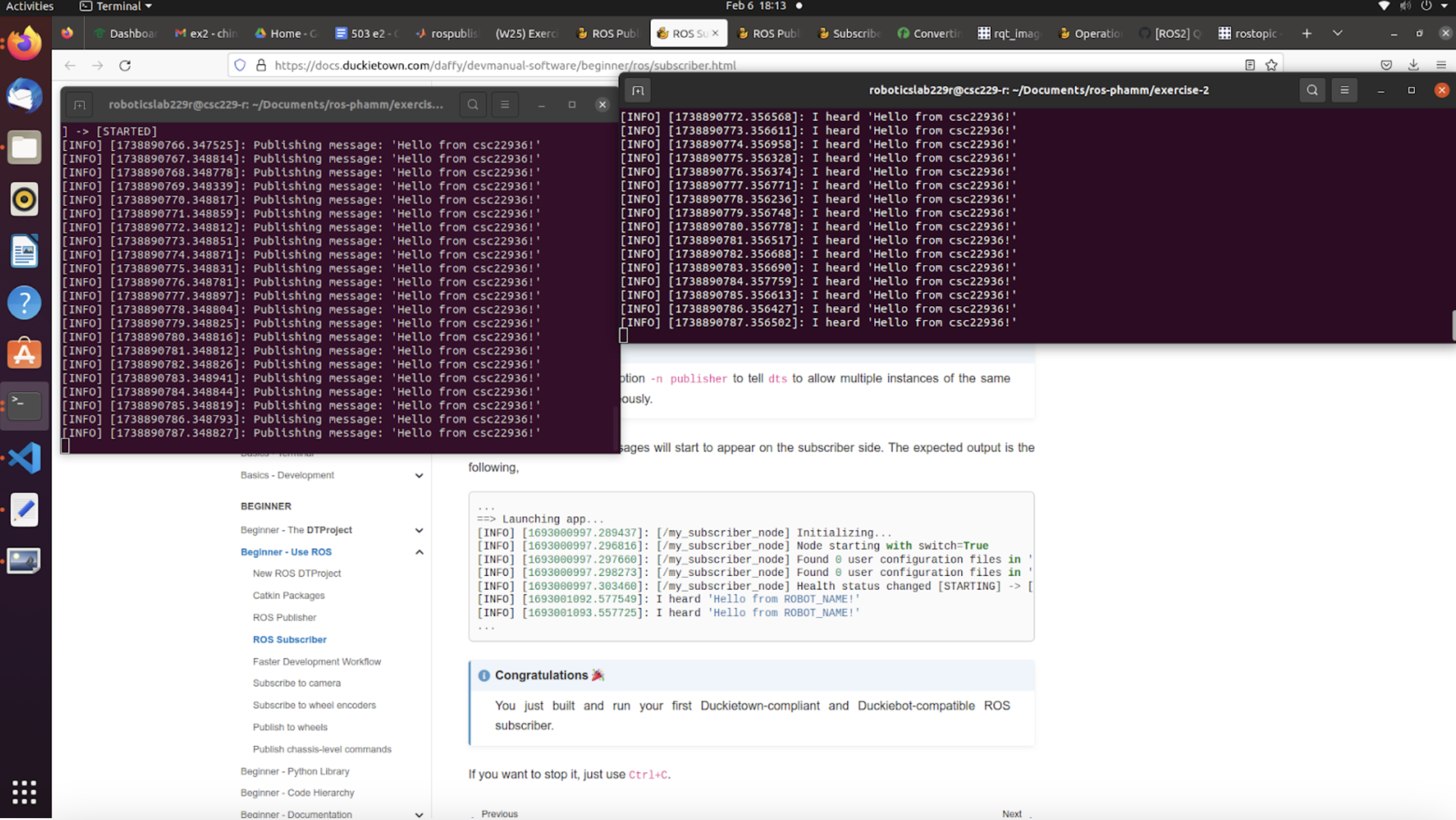
In this screenshot, it shows two running nodes we implemented - my_publisher_node and my_subscriber_node. The publisher node publishes the string message “Hello from csc22936!” to the topic chatter. The subscriber node subscribes to the same topic and logs “I heard ‘Hello from csc22936!’” to the terminal each time a message is received.
Screenshot of annotated custom camera image
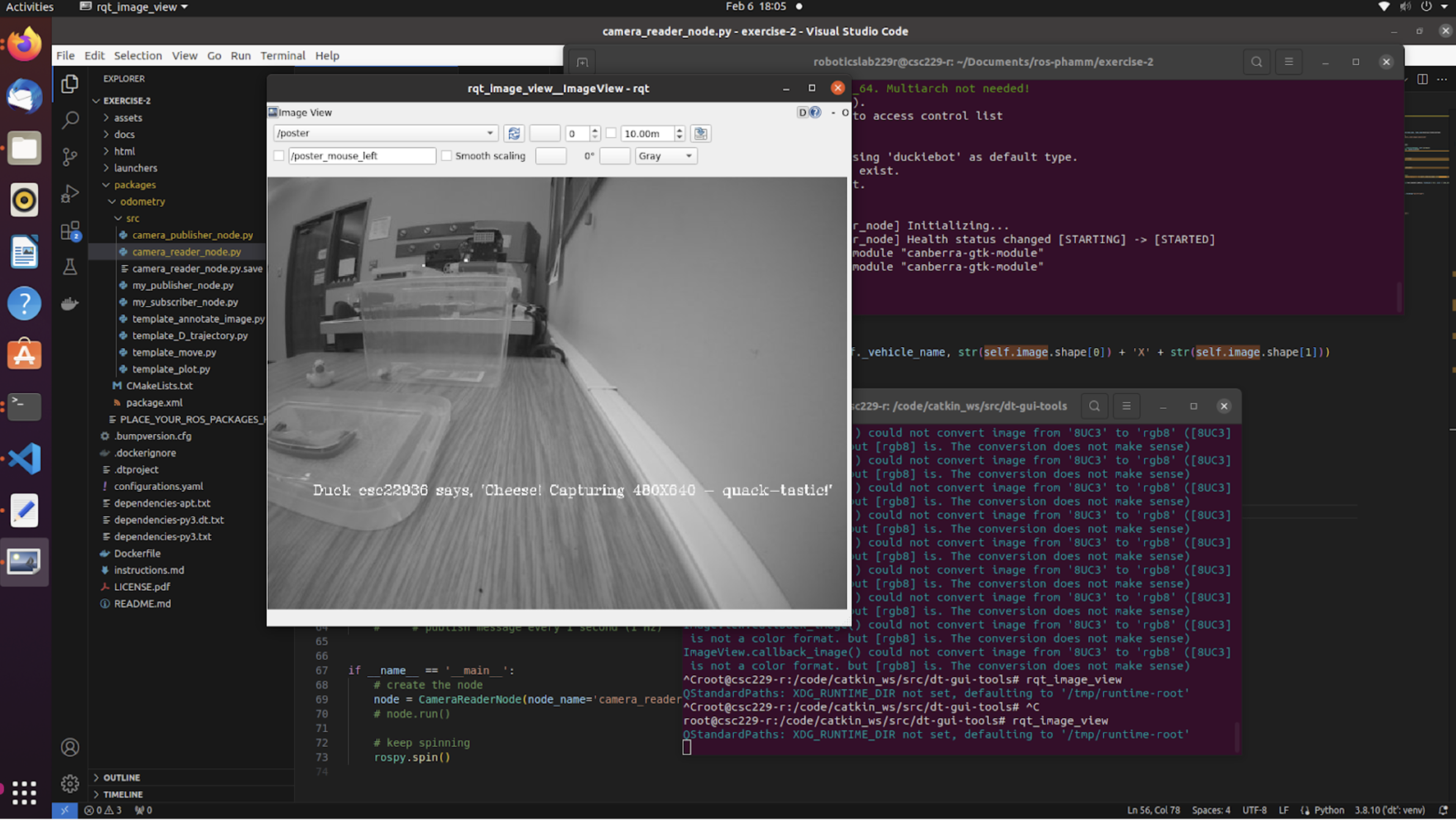
To achieve this display, we: (1) created a camera reader node that subscribes to the Duckiebot camera, (2) used cv2 to turn the camera display into gray scale and drew the text ‘Duck csc22936 says, ‘Cheese! Capturing on the camera’s display 480x640 - quack-tastic!’ onto the image, (3) published messages with sensor_msgs.msg.Image type to a custom topic named poster (4) chose the custom topic on rqt_image_view to view the final image.
Move the Duckiebot
Video of Duckiebot driving forward then backwards
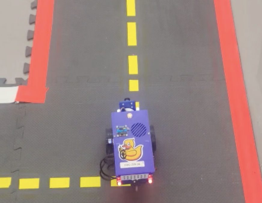
The video shows the Duckiebot moving forward for 1.25 m, pausing for 1 second, and backing for 1.25 m to stop close to the starting location. The node executing driving forth and back subscribes to the both right and left wheel encoder topics to retrieve the current tick and determines how far the robot has traveled on each wheel. Based on the estimated position of the Duckiebot, the node publishes to the wheels_driver_node/wheels_cmd topic to update the velocity of each wheel.
Why is there a difference between actual and desired location?
Our results show that when driving straight, the actual vertical distance travelled is accurate. The video also shows that the rotational and curving movements are more unpredictable. The causes are varying, but we suspect that in our case, the main culprits for any movement unpredictability are: (1) uneven flooring, which leads to variable contact pressure, and (2) mechanical wears, such as the misalignment of wheels, or the wearing down of wheel treads.
What speed did you use?
We used the default gain and trim parameter of the Duckiebot’s kinematics. Instead of tuning these parameters for calibration purposes, we scaled the velocity values in the messages published to the wheels. In other words, we used throttle multipliers to scale the published velecity values, achieving caliberation at the same time.
We ran the experiments at both higher speed (higher throttle multipliers) and low speed (lower throttle multipliers). Specifically:
- For high speed, the left throttle is 0.66, the right throttle is 0.7
- For low speed, the left throttle is 0.23, the right throttle is 0.3
What happens when you increae or decrease the speed?
From our observation, under this approach to speed manipulation, the wheels’ velocities do not scale at the same rate. For example, a differential-wheeled robot that can go straight under a certain configuration may not necessarily go straight if both the left and right throttle multipliers are doubled. The cause may be external dynamics (interactions with environments) rather than technical constraints (wheel velocity equations).
Our empirical results show that at higher speeds, the Duckiebot (1) is less affected by slight uneven flooring but (2) is more affected by large bumps, and (3), requires pauses when changing movement direction (for example, in the forth and back drive, we need to pause for one second before going back).
Turn the Duckiebot
Video of Duckiebot rotating clockwise and back
The video shows the Duckiebot rotating clockwise roughly 90 degrees, pausing for 1 second, and moving back to the original orientation. The node responsible for turning also subsribes from the wheel encoder topics to estimate the distance traveled by each wheel and publishes to wheels_driver_node/wheels_cmd topic to update the left and right wheel velocity. During a turning, the velocity of one wheel is unchanged and the velocity of the other wheel is reversed so that the robot ideally stays in the same position after a turn.
What could be the cause of deviations in the rotation?
The main causes of deviation could be due to (1) uneven flooring or unequal friction between contact surfaces, leading to discrepancies between the robot’s actual orientation and the calculated value from ticks, (2) mechanical or hardware issues, such as dust accumulation, motor wear, or wheel misalignment.
Plotting the tracked trajectory
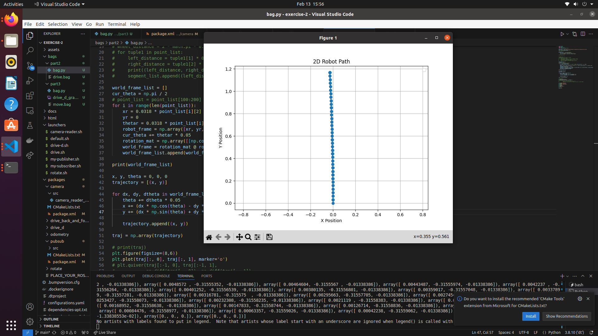
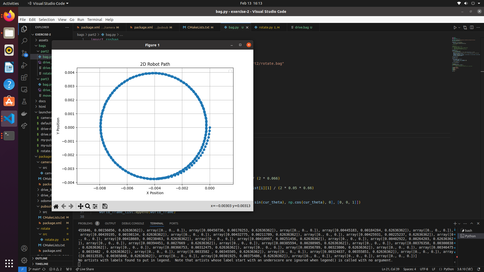
The two graphs above illustrate the robot’s path while driving straight for 1.25 meters forward and backward, as well as rotating 90 degrees in both directions. In the first graph, the x-position deviates by approximately 5 cm throughout the motion, while the y-position ranges from 0 to about 1.2 meters. This indicates that the Duckiebot maintained a relatively straight path with minimal horizontal errors. In the second graph, the robot’s trajectory suggests rotation around a central point. The circular pattern shown may reflect a slight deviation in the recorded center of rotation compared to the actual pivot point of the robot, potentially due to reasons such as inertia or inaccuracte measurement.
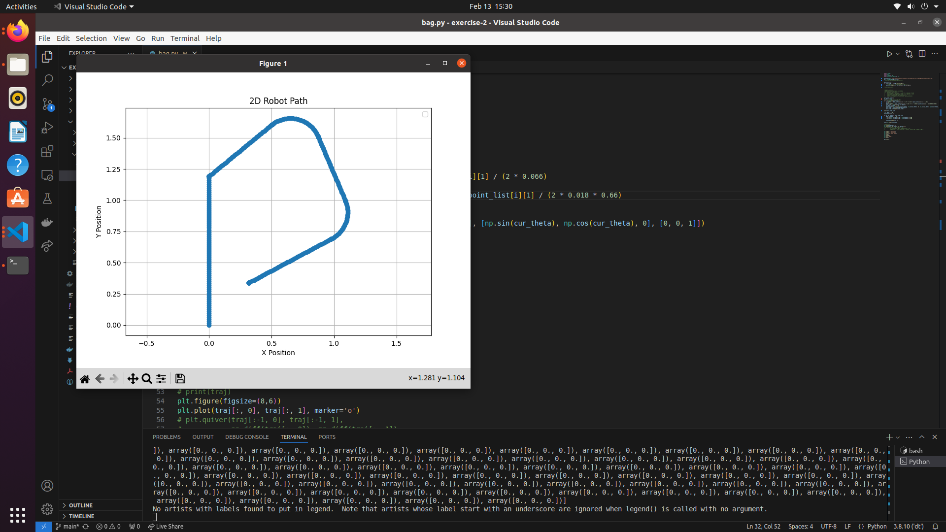
The graph above illustrates the robot’s path while tracing a “D”-shaped track. The robot successfully drove straight for up to 1.25 meters with minimal error. However, the ROS bag recorded a smaller turn angle than the actual 90-degree turn, leading to a noticeable deviation in the graph. As a result, the robot appears to move further along the y-axis in the plot than observed in the video. After this discrepancy, the recording accurately captured both the curve and the straight driving segments.
Duckiebot Pathing
Video of the Duckiebot driving in a “D” shape
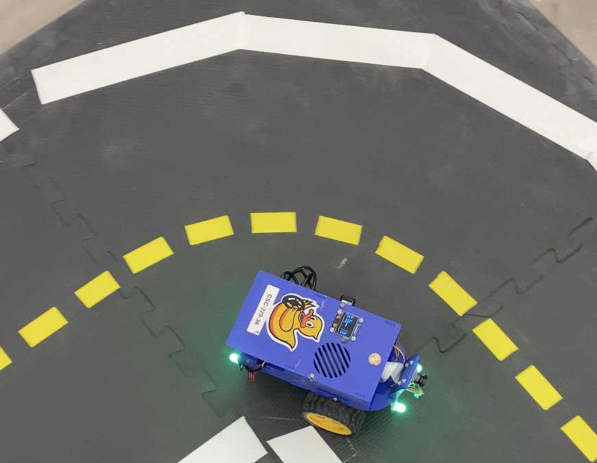
The video shows the Duckiebot driving in the “D” shape tracks and changing its colour between states. The Duckiebot performs position calculation and controls wheel velocity using the same method as described above. The total execution time accounting for all three states is 39 seconds.
LED mapping criteria
- In state 1, the Duckiebot starts stationary for 5 seconds. The LED light for this state is purple (rgb: [1, 0, 1]).
- In state 2, the Duckiebot is tracing the “D” path. The LED light for this state is green (rgb: [0, 1, 0]).
- In state 3, the Duckiebot returns to the starting position, waits for 5 seconds, and changes the LED light. The LED light for this state is blue (rgb: [0, 0, 1]).
Write Up
In this exercise, we learned to develop a fully functional ROS application. We set up DTROS, created a caitkin package, and developed publisher nodes and subscriber nodes that communicate with each other via topics. Specifically, we completed a series of tasks based on wheel encodings of the Duckiebot, such as making the Duckiebot drive straight, curve, rotate, and stop through rospy. We also worked on changing the LED light of the Duckiebot by publishing the messages to the LED emitter node. Through these tasks, we understood ROS basic concepts (such as ROS nodes, topics, and so on) better and learned to apply odometry modeling to hands-on robotics applications and to use rosbag to record and analyze odometry data.
This exercise taught us some practical lessons. First, robotics applications are hard: the results don’t always act in accordance with mathematical calculation because of extrernal factors, such as contact surfaces. Secondly, the quality of the hardware is very important for the consistent performance of the Duckiebot. We observed that Duckiebot doesn’t always have the left wheel and right wheel activate at the same time, and that phenomenon heavily affects the robot’s performance. Finally, proper perception would be very helpful in robotics applications. A big challenge of this exercise is having the robot to perform intended functions through just hard coding based on the data from wheel encoders. But code doesn’t adapt to a myriad of uncertainties and scenarios in the real world. So it would be very helpful if the robot can adapt based on its perception of the external world, such as using a camera .
Bonus
- Reverse parking
- Drive square
- Code
- We mentioned above that the accuracy of the wheels are highly affected by external factors, so any shifts in movements would affect the throttle scaling accuracy, straightness in driving, rotations, etc.., and hence the odometry. However, in our experience, this experiment was smooth beside the fact that there was some jerkiness in driving along one side of the square. This jerkiness could be attributed to the robot’s reaction.
References
Collboration
- The report is a joint effort by Alex Liu and Minh Pham on the completed deliverables of the lab, including the aformentioned screenshots and video, as well as the github repository.
- Questions regarding the lab were answered by TAs of the course.
AI Usages
- ChatGPT was used to reword some sentences in this report and to assist in coding.
Resources
- https://wiki.ros.org
- https://note.nkmk.me/en/python-opencv-pillow-image-size
- https://www.geeksforgeeks.org/python-grayscaling-of-images-using-opencv/
- https://docs.duckietown.com/daffy/devmanual-software/beginner/ros/index.html
- https://learnopencv.com/annotating-images-using-opencv/
- https://stackoverflow.com/questions/72690021/how-to-process-a-image-message-with-opencv-from-ros2
- https://docs-old.duckietown.org/daffy/duckietown-robotics-development/out/odometry_modeling.html
- https://docs.duckietown.com/daffy/dt-ros-commons/packages/duckietown_msgs.html
- https://community.robotshop.com/forum/t/2-wheel-drift/5636